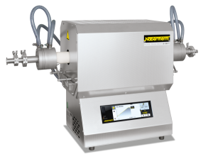
Tube Furnaces up to 1800 °C ACCESSORIES
Tube Furnaces up to 1800 °C ACCESSORIES
Gas Supply Systems 1

Gas Supply System 1 For Non-Flammable Protective or Reactive Gases in Static Tube Furnaces, not Gas-Tight
Gas supply system 1 is a basic version for static tube furnaces, for operation with non-flammable protective or reactive gases. This system is not completely gas-tight and can therefore not be used for vacuum operation.
Standard Equipment
- Available for RD, R, RT, RHTC, RSH and RSV tube furnaces
- Two plugs made of porous, non-classified ceramic fiber incl. protective gas connections
- The standard working tube supplied with the furnace can be used
- Gas panel for one non-flammable protective or reactive gas (N2, Ar, He, CO2, air, forming gas*)
- Shut-off valve and flow meter with manual valve
- Supply of gas with 300 mbar required
Gas Supply Systems 15 and 2
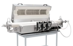
Gas Supply Systems 15 and 2 for Non-Flammable Protective or Reactive Gases in Static Tube Furnaces, Gas-Tight
For increased atmospheric purity requirements in the working tube in static tube furnaces we recommend one of these gas-tight gas supply systems with stainless steel flanges on the end of the tube is recommended.
The less expensive gas supply system 15 for furnaces up to 1300 °C and working tubes to 120 mm diameter is available for R, RSH and RSV tube furnaces. It includes contact protection on the flange and a stainless steel type 1.4301 heat radiation protection insert for the tube ends to protect the seals. A heat radiation protection package cools the flanges and a water connection is thus not required. With this variant, the tube must not be opened while it is hot. It is also not suitable for applications with a turbomolecular pump to achieve high vacuum. Gas supply system 2 is the correct choice for this type of application.
Gas supply system 2 with water-cooled flanges is available for R, RHTC, RHTH, RHTV, RSH and RSV furnaces. Cooling water supply with NW9 hose connector to be provided by the customer.
Standard Equipment
- Extended gas-tight working tube made of C 610 for furnaces up to 1300 °C or C 799 for temperatures above 1300 °C
- Two vacuum-tight stainless steel flanges with KF flange on the outlet side
- Mounting system on furnace for the flanges
- Gas panel for one non-flammable protective or reactive gas(N2, Ar, He, CO2, air, forming gas*)
- Shut-off valve and flow meter with manual valve
- Supply of gas with 300 mbar required
- Check valve in the gas outlet to prevent air entering
Additional Equipment for Gas Supply Systems 15 and 2
- Additional gas panels for further non-flammable gases
- Automatic segment-related switching on/off by a magnetic valve
- Bottle pressure reducer for use with bottled gas
- Vacuum package for a maximum final pressure of up to 5 x 10⁻⁵ mbar
Other Additional Equipment only for Gas Supply System 2
- Quick-locks for water-cooled flanges
- Air-water heat exchanger for closed loop water circuit
- Window for charge observation
| Model | Gas supply system | ||||||
|---|---|---|---|---|---|---|---|
| 1 | 15 | 2 | 25 | 26 | 3 | 4 | |
| RD | ● | ||||||
| R | ● | ● | ● | ● | ● | ||
| RT | ● | ||||||
| RHTC | ● | ● | ● | ● | |||
| RHTH | ● | ● | ● | ||||
| RHTV | ● | ● | ● | ||||
| RSH | ● | ● | ● | ● | ● | ||
| RSV | ● | ● | ● | ● | ● | ||
| RSRB | ● | ● | ● | ||||
| RSRC | ● | ● | ● | ||||
Gas Supply Systems 25 and 26
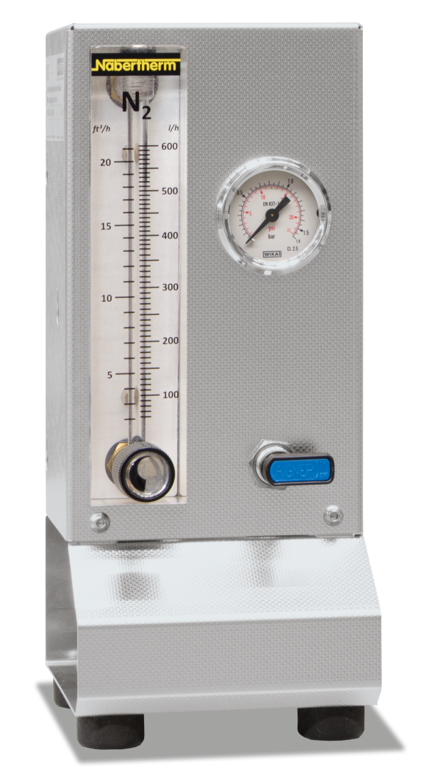
Gas Supply Systems 25 and 26 for Non-Flammable Protective or Reactive Gases in Rotary Tube Furnaces, Gas-Tight
Gas supply systems for non-flammable protective and reactive gases are also available for RSRB and RSRC rotary tube furnaces.
Standard Equipment
- Gas panel for one non-flammable protective or reactive gas (N2, Ar, He, CO2, air, forming gas*)
- Shut-off valve and flow meter with manual valve
- Supply of gas with 300 mbar required
- Gas supply system 25 for rotary tube furnaces for batch operation (RSRB) also includes gas-tight rotary lead-outs on the gas inlet and outlet as well as a gas cooler at the outlet. A check valve is also installed at the gas outlet to prevent air entering the tube.
- For gas supply system 26 for rotary tube furnaces for continuous processes (RSRC) the furnace must also be equipped with a feeding system.
Gas Supply System 3
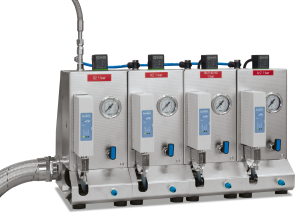
Gas supply system 3 allows for the operation in a hydrogen atmosphere at temperatures above 750 °C. From 750 °C, hydrogen can be introduced into the working tube. At program end or when the temperature falls below 750 °C , the working tube is purged with nitrogen to prevent the formation of an explosive hydrogen/oxygen atmosphere. The purging volume is at least five times the volume of the tube. Surplus hydrogen is burnt off in an exhaust gas torch.
Standard Equipment
- Available for R, RHTC, RHTH, RHTV, RSH, RSV, RSRB and RSRC tube furnaces
- Gas panel for hydrogen and nitrogen
- Automatic segment-related switching on/off by a magnetic valve
- Nabertherm Controller to regulate the temperature curve and switch the gas supply system
- Additional safety controls with touch panel to monitor hydrogen gassing only above 750 °C
- Exhaust gas torch with temperature monitoring
- Over-temperature limiter with digital display as over-temperature protection for the furnace and charge
- Temperature monitoring at the gas inlet
- Emergency purge container for nitrogen
- Additional gas panels for further non-flammable gases
- Gassing via program-related controllable mass flow controllers
- Bottle pressure reducer for use with bottled gas
- Air-water heat exchanger for closed loop water circuit (not for RSRB and RSRC)
| Model | Gas supply system | ||||||
|---|---|---|---|---|---|---|---|
| 1 | 15 | 2 | 25 | 26 | 3 | 4 | |
| RD | ● | ||||||
| R | ● | ● | ● | ● | ● | ||
| RT | ● | ||||||
| RHTC | ● | ● | ● | ● | |||
| RHTH | ● | ● | ● | ||||
| RHTV | ● | ● | ● | ||||
| RSH | ● | ● | ● | ● | ● | ||
| RSV | ● | ● | ● | ● | ● | ||
| RSRB | ● | ● | ● | ||||
| RSRC | ● | ● | ● | ||||
Gas Supply System 4
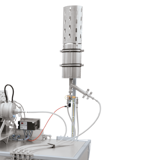
Gas Supply System 4 for Hydrogen Applications in Tube Furnaces from Room Temperature
Gas supply system 4 allows operation with a hydrogen atmosphere starting at ambient temperature. During hydrogen operation, a pressure of approx. 30 mbar is ensured in the working tube. At the gas outlet the hydrogen is burnt off in an exhaust gas torch. Equipped with a safety PLC control system, pre-purging, hydrogen inlet, operation, fault monitoring and purging at the end of the process are carried out automatically (with at least five times the volume of the tube). If a malfunction occurs, the tube is immediately purged with nitrogen and the system is automatically switched to a safe status.
Standard Equipment
- Available for R, RHTC, RHTH, RHTV, RSH, RSV, RSRB and RSRC tube furnaces
- Gas panel for hydrogen and nitrogen
- Automatic segment-related switching on/off by a magnetic valve
- Control via safety PLC control system with touch panel
- Exhaust gas torch with temperature monitoring
- Over-temperature limiter with digital display as over-temperature protection for the furnace and charge
- Excess pressure monitoring
- Emergency purge container for nitrogen
- Additional gas panels for further non-flammable gases
- Operation with other flammable gases
- Gassing via program-related controllable mass flow controllers
- Bottle pressure reducer for use with bottled gas
- Air-water heat exchanger for closed loop water circuit (apart from RSRB and RSRC)
| Model | Gas supply system | ||||||
|---|---|---|---|---|---|---|---|
| 1 | 15 | 2 | 25 | 26 | 3 | 4 | |
| RD | ● | ||||||
| R | ● | ● | ● | ● | ● | ||
| RT | ● | ||||||
| RHTC | ● | ● | ● | ● | |||
| RHTH | ● | ● | ● | ||||
| RHTV | ● | ● | ● | ||||
| RSH | ● | ● | ● | ● | ● | ||
| RSV | ● | ● | ● | ● | ● | ||
| RSRB | ● | ● | ● | ||||
| RSRC | ● | ● | ● | ||||
Vacuum Package
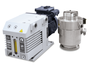
The vacuum package enables the working tube to be evacuated for vacuum operation in tube furnaces. It consists of an intermediate component for the gas outlet, a ball valve, a pressure gauge and a manually operated vacuum pump that is connected to the gas outlet by a corrugated stainless steel hose. A gas-tight furnace system is required for the use of a vacuum package, e.g. with the gas-supply packages 15, 2, 25 or 26. To protect the vacuum pump, only cold stage evacuation is allowed. The pump can then remain switched during the running program. The maximum ultimate pressure in the working tube depends on the type of pump.
- Single-stage rotary vane pump for an achievable ultimate pressure of approx. 20 mbar
- Two-stage rotary vane pump for an achievable ultimate pressure of approx. 5 x 10⁻² mbar
- Turbomolecular pump system, consisting of a diaphragm pump with downstream turbomolecular pump for an achievable ultimate pressure of up to approx. 5 x 10⁻⁵ mbar (not for models RSRB and RSRC and not in combination with gas supply package 15)
| Model | Gas supply system | ||||||
|---|---|---|---|---|---|---|---|
| 1 | 15 | 2 | 25 | 26 | 3 | 4 | |
| RD | ● | ||||||
| R | ● | ● | ● | ● | ● | ||
| RT | ● | ||||||
| RHTC | ● | ● | ● | ● | |||
| RHTH | ● | ● | ● | ||||
| RHTV | ● | ● | ● | ||||
| RSH | ● | ● | ● | ● | ● | ||
| RSV | ● | ● | ● | ● | ● | ||
| RSRB | ● | ● | ● | ||||
| RSRC | ● | ● | ● | ||||
Controls for Tube Furnaces
Furnace Chamber and Charge Controls
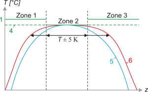
With the furnace chamber control, the temperature is only measured in the furnace chamber outside the working tube. This protects the thermocouples from damage and aggressive batch. The control is slow to avoid overshoots. Since the temperature inside the working tube is not measured in this mode, a significant temperature difference can occur between the batch temperature inside the tube and the furnace chamber temperature displayed in the controller. With an additional charge thermocouple, the “charge control” mode can measure the temperature in the furnace as well as the temperature inside the working tube. This enables the batch temperature to be controlled very precisely and quickly. Charge control can be used with all tube furnaces, with the exception of the RD and RT series.
Three-Zone Furnace Chamber Controls
The heated length is divided into three heating zones. The temperature is measured via one thermocouple per zone, which is positioned outside the working tube between the heating wires. The side zones are controlled via a setpoint offset in relation to the middle zone. In this way, the heat loss at the tube ends can be compensated in order to achieve an extended zone of constant temperature (+/− 5 K).
Freely Radiating Heating Elements
A very good temperature uniformity is achieved with the freely radiating heating elements on support tubes.
