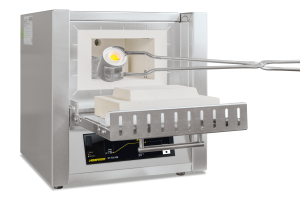
Muffle Furnaces up to 1400 °C
Muffle Furnaces up to 1400 °C
Muffle Furnaces up to 1100 °C or 1200 °C
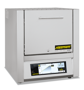
The muffle furnaces L 1/12 – LT 40/12 have been proven for daily laboratory use. These models stand out for their excellent workmanship, advanced and attractive design, and high level of reliability. The muffle furnaces come equipped with either a flap door or lift door at no extra charge.
Standard Equipment
- Tmax 1100 °C or 1200 °C
- Heating from two sides by ceramic heating plates (heating from three sides for muffle furnaces L 24/11 – LT 40/12) for an optimal temperature uniformity
- Temperature uniformity of +/− 5 K with closed fresh-air inlet in empty work space according to DIN 17052-1 at working temperatures above 800 °C
- Thermocouple type N (1100 °C) or type S (1200 °C)
- Ceramic heating plates with integral heating element which is safeguarded and easy to replace
- Optional flap door (L) or lift door (LT) with hot surface facing away from the operator
- Dual shell housing made of textured stainless steel sheets with additional fan cooling for low surface temperature
- Exclusive use of insulation materials without categorization according to EC Regulation No. 1272/2008 (CLP)
- Adjustable air inlet integrated in door (see illustration)
- Exhaust air outlet in rear wall of furnace
- Controller B510 resp. R7 for L 1/12 (5 programs with each 4 segments)
- Solid state relays provide for lownoise operation
- Defined application within the constraints of the operating instructions
- NTLog Basic for Nabertherm controller: recording of process data with USB-flash drive
- Chimney, chimney with fan or catalytic converter (not for L 1 and L 15)
- Over-temperature limiter with adjustable cutout temperature as temperature limiter to protect the furnace and load
- Protective gas connection to purge with non-flammable protective or reaction gases (not available in combination with chimney, chimney with fan or catalytic converter) not gas tight
- Manual or automatic gas supply system
- Port for thermocouple in the rear wall or in the furnace door
- Process control and documentation via VCD software package for monitoring, documentation and control
- Charging rack with closed or perforated trays for loading the furnace in two levels incl. holder for inserting/removing the trays up to a max. temperature of 800 °C and a max. loading weight per layer of 2 kg for the L(T) 9/11 respectively 3 kg for the L(T) 15/11
| Model | Tmax | Inner dimensions in mm | Volume | Outer dimensions2 in mm | Temperature uniformity of +/− 5K in the empty workspace5 | Connected load | Electrical | Weight | Heating time | ||||||
|---|---|---|---|---|---|---|---|---|---|---|---|---|---|---|---|
| in °C1 | w | d | h | in l | W | D | H3 | w | d | h | in kW | connection* | in kg | in min4 | |
| L(T) 3/11 | 1100 | 160 | 140 | 100 | 3 | 385 | 330 | 405+155 | 110 | 50 | 50 | 1.2 | 1-phase | 20 | 40 |
| L(T) 5/11 | 1100 | 200 | 170 | 130 | 5 | 385 | 390 | 460+205 | 170 | 80 | 90 | 2.4 | 1-phase | 30 | 50 |
| L(T) 9/11 | 1100 | 230 | 240 | 170 | 9 | 415 | 455 | 515+240 | 180 | 150 | 120 | 3.0 | 1-phase | 35 | 65 |
| L(T) 15/11 | 1100 | 230 | 340 | 170 | 15 | 415 | 555 | 515+240 | 180 | 250 | 120 | 3.2 | 1-phase | 40 | 75 |
| L(T) 24/11 | 1100 | 280 | 340 | 250 | 24 | 490 | 555 | 580+320 | 230 | 250 | 200 | 4.5 | 3-phase | 55 | 70 |
| L(T) 40/11 | 1100 | 320 | 490 | 250 | 40 | 530 | 705 | 580+320 | 270 | 400 | 200 | 6.0 | 3-phase | 65 | 75 |
| L 1/12 | 1200 | 90 | 115 | 110 | 1 | 290 | 280 | 430 | 45 | 60 | 40 | 1.5 | 1-phase | 10 | 25 |
| L(T) 3/12 | 1200 | 160 | 140 | 100 | 3 | 385 | 330 | 405+155 | 110 | 50 | 50 | 1.2 | 1-phase | 20 | 45 |
| L(T) 5/12 | 1200 | 200 | 170 | 130 | 5 | 385 | 390 | 460+205 | 170 | 80 | 90 | 2.4 | 1-phase | 30 | 60 |
| L(T) 9/12 | 1200 | 230 | 240 | 170 | 9 | 415 | 455 | 515+240 | 180 | 150 | 120 | 3.0 | 1-phase | 35 | 75 |
| L(T) 15/12 | 1200 | 230 | 340 | 170 | 15 | 415 | 555 | 515+240 | 180 | 250 | 120 | 3.2 | 1-phase | 40 | 85 |
| L(T) 24/12 | 1200 | 280 | 340 | 250 | 24 | 490 | 555 | 580+320 | 230 | 250 | 200 | 4.5 | 3-phase | 55 | 80 |
| L(T) 40/12 | 1200 | 320 | 490 | 250 | 40 | 530 | 705 | 580+320 | 270 | 400 | 200 | 6.0 | 3-phase | 65 | 85 |
| 1Recommended working temperature for processes with longer dwell times is 1000 °C (L../11) rsp. 1100 °C (L../12)*Please see page 75 for more information about supply voltage 2External dimensions vary when furnace is equipped with additional equipment. Dimensions on request. 3Including opened lift door (LT models) 4Heating time of the empty and closed furnace up to Tmax −100 K (connected to 230 V 1/N/PE rsp. 400 V 3/N/PE) 5Temperature uniformity of +/− 5 K with closed fresh-air inlet in empty work space according to DIN 17052-1 at working temperatures above 800 °C | |||||||||||||||
Economy Muffle Furnaces up to 1100 °C

With their convincing price/performance ratio and the fast heat-up rates, these compact muffle furnaces are perfect for many applications in the laboratory. Quality features like the dual shell furnace housing of rust-free stainless steel, their compact, lightweight constructions, or the heating elements encased in quartz glass tubes make these models reliable partners for your application.
Standard Equipment
- Tmax 1100 °C
- Heating from two sides from heating elements protected in quartz glass tubes
- Fast heating times (see table)
- Maintenance-friendly replacement of heating elements and insulation
- Housing coated in RAL 9003
- Solid state relays provide for lownoise operation
- Dual shell housing made of textured stainless steel sheets with additional fan cooling for low surface temperature
- Exclusive use of insulation materials without categorization according to EC Regulation No. 1272/2008 (CLP)
- Flap door which can also be used as a work platform
- Exhaust air outlet in rear wall
- Compact dimensions and light weight
- Controller mounted under the door to save space
- Controller R7
- Defined application within the constraints of the operating instructions
Chimney, chimney with fan or catalytic converter (not for LE 1 and LE 2)
- Chimney, chimney with fan or catalytic converter (not for LE 1 and LE 2)
| Model | Tmax | Inner dimensions in mm | Volume | Outer dimensions2 in mm | Temperature uniformity of +/− 5K in the empty workspace4 | Connected | Electrical | Weight | Heating time | ||||||
|---|---|---|---|---|---|---|---|---|---|---|---|---|---|---|---|
| in °C1 | w | d | h | in l | W | D | H | w | d | h | load in kW | connection* | in kg | in min3 | |
| LE 1/11 | 1100 | 90 | 115 | 110 | 1 | 290 | 280 | 410 | 40 | 65 | 60 | 1.6 | 1-phase | 15 | 10 |
| LE 2/11 | 1100 | 110 | 180 | 110 | 2 | 330 | 390 | 410 | 60 | 130 | 60 | 1.9 | 1-phase | 20 | 15 |
| LE 6/11 | 1100 | 170 | 200 | 170 | 6 | 390 | 440 | 470 | 120 | 150 | 120 | 2.0 | 1-phase | 27 | 30 |
| LE 14/11 | 1100 | 220 | 300 | 220 | 14 | 440 | 540 | 520 | 170 | 250 | 170 | 3.2 | 1-phase | 35 | 35 |
| LE 24/11 | 1100 | 260 | 330 | 280 | 24 | 490 | 570 | 590 | 200 | 270 | 230 | 3.5 | 1-phase | 42 | 40 |
| 1Recommended working temperature for processes with longer dwell times is 1050 °C*Please see page 75 for more information about supply voltage 2External dimensions vary when furnace is equipped with additional equipment. Dimensions on request. 3Heating time of the empty and closed furnace up to Tmax −100 K (connected to 230 V 1/N/PE) 4Temperature uniformity of +/− 5 K with closed fresh-air inlet in empty work space according to DIN 17052-1 at working temperatures above 800 °C | |||||||||||||||
Muffle Furnaces with Brick Insulation up to 1300 °C
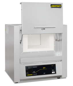
Heating elements on support tubes radiating freely into the furnace chamber provide for particularly short heating times for these muffle furnaces. Thanks to their robust lightweight refractory brick insulation, they can reach a maximum working temperature of 1300 °C. These muffle furnaces thus represent an interesting alternative to the familiar L(T) ../12 models, when you need a higher application temperature.
Standard Equipment
- Tmax 1300 °C
- Heating from two sides
- Heating elements on support tubes ensure free heat radiation and a long service life
- Multi-layer insulation with robust lightweight refractory bricks in the furnace chamber
- Dual shell housing made of textured stainless steel sheets with additional fan cooling for low surface temperature
- Optional flap door (L) which can be used as work platform or lift door (LT) with hot surface facing away from the operator
- Adjustable air inlet in the furnace door
- Exhaust air outlet in rear wall of furnace
- Controller B510 (5 programs with each 4 segments)
- Solid state relays provide for lownoise operation
- Defined application within the constraints of the operating instructions
- NTLog Basic for Nabertherm controller: recording of process data with USB-flash drive
- Chimney, chimney with fan or catalytic converter
- Over-temperature limiter with adjustable cutout temperature as temperature limiter to protect the furnace and load
- Protective gas connection to purge with non-flammable protective or reaction gases (not available in combination with chimney, chimney with fan or catalytic converter) not gas tight
- Manual or automatic gas supply system
- Port for thermocouple in the rear wall or in the furnace door
- Process control and documentation via VCD software package for monitoring, documentation and control
| Model | Tmax | Inner dimensions in mm | Volume | Outer dimensions2 in mm | Temperature uniformity of +/− 5K in the empty workspace5 | Connected load | Electrical | Weight | Heating time | ||||||
|---|---|---|---|---|---|---|---|---|---|---|---|---|---|---|---|
| in °C1 | w | d | h | in l | W | D | H3 | w | d | h | in kW | connection* | in kg | in min4 | |
| L, LT 5/13 | 1300 | 200 | 170 | 130 | 5 | 490 | 450 | 580+320 | 170 | 100 | 80 | 2.4 | 1-phase | 42 | 60 |
| L, LT 9/13 | 1300 | 230 | 240 | 170 | 9 | 530 | 525 | 630+350 | 180 | 170 | 120 | 3.0 | 1-phase | 60 | 60 |
| L, LT 15/13 | 1300 | 230 | 340 | 170 | 15 | 530 | 625 | 630+350 | 180 | 270 | 120 | 3.2 | 1-phase | 70 | 70 |
| 1Recommended working temperature for processes with longer dwell times is 1200 °C*Please see page 75 for more information about supply voltage 2External dimensions vary when furnace is equipped with additional equipment. Dimensions on request. 3Including opened lift door (LT models) 4Heating time of the empty and closed furnace up to Tmax −100 K (connected to 230 V 1/N/PE) 5Temperature uniformity of +/− 5 K with closed fresh-air inlet in empty work space according to DIN 17052-1 at working temperatures above 800 °C | |||||||||||||||
Muffle Furnaces up to 1400 °C

These models stand out for their excellent workmanship, advanced and attractive design, and high level of reliability. Heating elements on support tubes radiating freely into the furnace chamber provide for particularly short heating times and a maximum temperature of 1400 °C. These muffle furnaces are a good alternative to the familiar L(T) ../12 series when higher application temperatures are needed.
Standard Equipment
- Tmax 1400 °C
- Heating from two sides
- Heating elements on support tubes ensure free heat radiation and a long service life
- Dual shell housing made of textured stainless steel sheets with additional fan cooling for low surface temperature
- Exclusive use of insulation materials without categorization according to EC Regulation No. 1272/2008 (CLP)
- Adjustable air inlet integrated in door
- Exhaust air outlet in rear wall of furnace
- Controller B510 (5 programs with each 4 segments)
- Solid state relays provide for lownoise operation
- Defined application within the constraints of the operating instructions
- NTLog Basic for Nabertherm controller: recording of process data with USB-flash drive
- Chimney, chimney with fan or catalytic converter
- Over-temperature limiter with adjustable cutout temperature as temperature limiter to protect the furnace and load
- Protective gas connection to purge with non-flammable protective or reaction gases (not available in combination with chimney, chimney with fan or catalytic converter), not gas tight
- Manual or automatic gas supply system
- Process control and documentation via VCD software package for monitoring, documentation and control
| Model | Tmax | Inner dimensions in mm | Volume | Outer dimensions2 in mm | Temperature uniformity of +/− 5K in the empty workspace5 | Connected load | Electrical | Weight | Heating time | ||||||
|---|---|---|---|---|---|---|---|---|---|---|---|---|---|---|---|
| in °C1 | w | d | h | in l | W | D | H3 | w | d | h | in kW | connection* | in kg | in min4 | |
| L, LT 5/14 | 1400 | 200 | 170 | 130 | 5 | 490 | 450 | 580+320 | 170 | 120 | 80 | 2.4 | 1-phase | 42 | 50 |
| L, LT 9/14 | 1400 | 250 | 250 | 170 | 9 | 530 | 525 | 630+350 | 180 | 190 | 120 | 3.2 | 1-phase | 55 | 50 |
| L, LT 15/14 | 1400 | 250 | 350 | 170 | 15 | 530 | 625 | 630+350 | 180 | 290 | 120 | 3.2 | 1-phase | 63 | 70 |
| 1Recommended working temperature for processes with longer dwell times is 1300 °C 2External dimensions vary when furnace is equipped with additional equipment. Dimensions on request. 3Including opened lift door 4Heating time of the empty and closed furnace up to Tmax −100 K (connected to 230 V 1/N/PE) 5Temperature uniformity of +/− 5 K with closed fresh-air inlet in empty work space according to DIN 17052-1 at working temperatures above 800 °C | |||||||||||||||
Muffle Furnaces with Embedded Heating Elements in the Ceramic Muffle up to 1100 °C
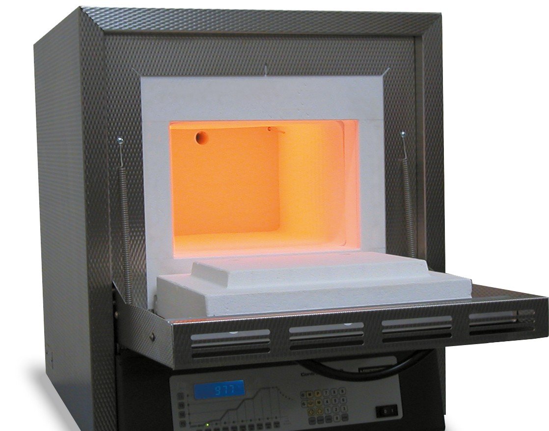
We particularly recommend the muffle furnace L 9/11/SKM for heat treatment of aggressive substances. The furnace has a ceramic muffle with embedded heating from four sides. The muffle furnace thus combines a very good temperature uniformity with excellent protection of the heating elements from aggressive atmospheres. Another aspect is the smooth, nearly particle free muffle (furnace door made of fiber insulation), an important quality feature.
Standard Equipment
- Tmax 1100 °C
- Muffle heated from four sides
- Furnace chamber with embedded ceramic muffle, high resistance to aggressive gasses and vapours
- Dual shell housing made of textured stainless steel sheets with additional fan cooling for low surface temperature
- Exclusive use of insulation materials without categorization according to EC Regulation No. 1272/2008 (CLP)
- Optional flap door (L) which can be used as work platform or lift door (LT) with hot surface facing away from the operator
- Adjustable working air inlet in the door
- Exhaust air outlet in rear wall of furnace
- Controller B510 (5 programs with each 4 segments)
- Solid state relays provide for lownoise operation
- Defined application within the constraints of the operating instructions
- NTLog Basic for Nabertherm controller: recording of process data with USB-flash drive
- Chimney, chimney with fan or catalytic converter
- Over-temperature limiter with adjustable cutout temperature as temperature limiter to protect the furnace and load
- Protective gas connection to purge with non-flammable protective or reaction gases (not available in combination with chimney, chimney with fan or catalytic converter) not gas tight
- Manual or automation gas supply system
- Port for thermocouple in the rear wall or in the furnace door
- Process control and documentation via VCD software package for monitoring, documentation and control
| Modell | Tmax | Inner dimensions in mm | Volume | Outer dimensions2 in mm | Connected | Electrical | Weight | Heating time | ||||
|---|---|---|---|---|---|---|---|---|---|---|---|---|
| in °C1 | w | d | h | in l | W | D | H | load in kW | connection* | in kg | in min4 | |
| L 9/11/SKM | 1100 | 230 | 240 | 170 | 9 | 490 | 505 | 580 | 3.4 | 1-phase | 50 | 75 |
| LT 9/11/SKM | 1100 | 230 | 240 | 170 | 9 | 490 | 505 | 580+3203 | 3.4 | 1-phase | 50 | 75 |
| 1Recommended working temperature for processes with longer dwell times is 1000 °C*Please see page 75 for more information about supply voltage 2External dimensions vary when furnace is equipped with additional equipment. Dimensions on request. 3Including opened lift door 4Heating time of the empty and closed furnace up to Tmax −100 K (connected to 230 V 1/N/PE) | ||||||||||||
Ashing Furnaces up to 1100 °C
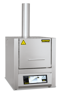
Ashing furnace LV ../11 is designed especially for ashing processes to 1050 °C in the laboratory. Applications include determining loss on ignition, ashing food and plastics for subsequent substance analysis. A special fresh-air and exhaust air system ensures that the air is replaced 6 times per minute so that there is always sufficient oxygen for the ashing process. Incoming air passes the furnace heating and is pre-heated to ensure good temperature uniformity.
Standard Equipment
- Tmax 1100 °C
- Heating from two sides
- Ceramic heating plates with integral heating element which is safeguarded, and easy to replace
- Air exchange of more than 6 times per minute
- Good temperature uniformity due to preheating of incoming air, temperature uniformity according to DIN 17052-1 to +/− 10 °C in the defined empty work area (from 550 °C)
- Dual shell housing made of textured stainless steel sheets with additional fan cooling for low surface temperature
- Exclusive use of insulation materials without categorization according to EC Regulation No. 1272/2008 (CLP)
- Suitable for many standardized ashing processes according to ISO, ASTM, EN, and DIN
- Optional flap door (LV) which can be used as work platform or lift door (LVT) with hot surface facing away from the operator
- Controller B510 (5 programs with each 4 segments)
- Solid state relays provide for lownoise operation
- Defined application within the constraints of the operating instructions
- NTLog Basic for Nabertherm controller: recording of process data with USB-flash drive
- Over-temperature limiter with adjustable cutout temperature as temperature limiter to protect the furnace and load
- Port for thermocouple in the rear wall or in the furnace door
- Charging rack with closed or perforated trays for loading the furnace in two levels incl. holder for inserting/removing the trays up to a max. temperature of 800 °C and a max. loading weight per layer of 2 kg for the LV(T) 9/11 respectively 3 kg for the LV(T) 15/11
- Process control and documentation via VCD software package for monitoring, documentation and control
| Model | Tmax | Inner dimensions in mm | Volume | Outer dimensions2 in mm | Max. weight of hydrocarbons | Max. evaporation rate | Connected load | Electrical | Weight | Heating time | ||||
|---|---|---|---|---|---|---|---|---|---|---|---|---|---|---|
| Flap door | in °C1 | w | d | h | in l | W | D | H3 | in g | g/min | in kW | connection* | in kg | in min4 |
| LV 3/11 | 1100 | 160 | 140 | 100 | 3 | 385 | 360 | 735 | 5 | 0.1 | 1.2 | 1-phase | 20 | 45 |
| LV 5/11 | 1100 | 200 | 170 | 130 | 5 | 385 | 420 | 790 | 10 | 0.2 | 2.4 | 1-phase | 35 | 55 |
| LV 9/11 | 1100 | 230 | 240 | 170 | 9 | 415 | 485 | 845 | 15 | 0.3 | 3.0 | 1-phase | 45 | 70 |
| LV 15/11 | 1100 | 230 | 340 | 170 | 15 | 415 | 585 | 845 | 25 | 0.3 | 3.5 | 1-phase | 55 | 80 |
| Model | Tmax | Inner dimensions in mm | Volume | Outer dimensions2 in mm | Max. weight of hydrocarbons | Max. evaporation rate | Connected load | Electrical | Weight | Heating time | ||||
|---|---|---|---|---|---|---|---|---|---|---|---|---|---|---|
| Lift door | in °C1 | w | d | h | in l | W | D | H3 | in g | g/min | in kW | connection* | in kg | in min4 |
| LVT 3/11 | 1100 | 160 | 140 | 100 | 3 | 385 | 360 | 735 | 5 | 0.1 | 1.2 | 1-phase | 20 | 45 |
| LVT 5/11 | 1100 | 200 | 170 | 130 | 5 | 385 | 420 | 790 | 10 | 0.2 | 2.4 | 1-phase | 35 | 55 |
| LVT 9/11 | 1100 | 230 | 240 | 170 | 9 | 415 | 485 | 845 | 15 | 0.3 | 3.0 | 1-phase | 45 | 70 |
| LVT 15/11 | 1100 | 230 | 340 | 170 | 15 | 415 | 585 | 845 | 25 | 0.3 | 3.5 | 1-phase | 55 | 80 |
| 1Recommended working temperature for processes with longer dwell times is 1000 °C*Please see page 75 for more information about supply voltage 2External dimensions vary when furnace is equipped with additional equipment. Dimensions on request. 3Including exhaust tube (Ø 80 mm) 4Approx. heating time of the empty and closed furnace up to Tmax −100 K (connected to 230 V 1/N/PE) | ||||||||||||||
Ashing Furnaces with Integrated Exhaust Gas Cleaning up to 1100 °C
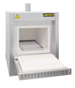
The ashing furnace L ../11 BO is specially designed for processes in which larger sample quantities have to be incinerated. Fields of application are e.g. the ashing of food, thermal cleaning of injection molding tools or the determination of annealing loss. Another application is the debinding of ceramic products, e.g. after additive production.
The ashing furnaces have a passive safety system and integrated exhaust gas post combustion. An exhaust gas fan extracts flue gases from the furnace and simultaneously supplies fresh air to the furnace atmosphere with the result that sufficient oxygen is always available for the incineration process. The incoming air is guided behind the furnace heating and preheated to ensure good temperature uniformity. Exhaust gases are led from the furnace chamber to the integrated post combustion system, where they are postburned and catalytically cleaned. Directly after the incineration process (up to max. 600 °C) a subsequent process up to max. 1100 °C can take place.
Standard Equipment
- Tmax 600 °C for the incineration process
- Tmax 1100 °C for the subsequent process
- Three-side heating (both sides and bottom)
- Ceramic heating plates with embedded heating wire
- Dual shell housing made of textured stainless steel sheets with additional fan cooling for low surface temperature
- Exclusive use of insulation materials without categorization according to EC Regulation No. 1272/2008 (CLP)
- Steel collecting pan protects the bottom insulation
- Spring-assisted closing of the furnace door (flap door) with mechanical locking against unintentional opening
- Thermal/catalytic post combustion, integrated in the exhaust channel, up to 600 °C in function
- Temperature control of post combustion can be set up to 850 °C
- Monitored exhaust air
- Inlet-air preheated through the bottom heating plate
- Over-temperature limiter with adjustable cutout temperature as temperature limiter to protect the furnace and load
- Controller C550 (10 programs with each 20 segments)
- Defined application within the constraints of the operating instructions
- NTLog Basic for Nabertherm controller: recording of process data with USB-flash drive
Process control and documentation via VCD software package for monitoring, documentation and control
- Process control and documentation via VCD software package for monitoring, documentation and control
| Model | Tmax | Inner dimensions in mm | Volume | Outer dimensions2 in mm | Max. weight of hydrocarbons | Max. evaporation rate | Connected load | Electrical | Weight | ||||
|---|---|---|---|---|---|---|---|---|---|---|---|---|---|
| in °C1 | w | d | h | in l | W | D | H3 | in g | g/min | in kW | connection* | in kg | |
| L 9/11 BO | 1100 | 230 | 240 | 170 | 9 | 415 | 575 | 750 | 75 | 1.0 | 7.0 | 3-phase | 60 |
| L 24/11 BO | 1100 | 280 | 340 | 250 | 24 | 490 | 675 | 800 | 150 | 2.0 | 9.0 | 3-phase | 90 |
| L 40/11 BO | 1100 | 320 | 490 | 250 | 40 | 530 | 825 | 800 | 200 | 2.1 | 11.5 | 3-phase | 110 |
| 1Recommended working temperature for processes with longer dwell times is 1000 °C*Please see page 75 for more information about supply voltage 2External dimensions vary when furnace is equipped with additional equipment. Dimensions on request. | |||||||||||||
Muffle Furnace incl. Scale and Software for Determination of Combustion Loss
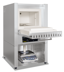
This weighing furnace with integrated precision scale and software, was designed especially for combustion loss determination in the laboratory. The determination of combustion loss is necessary, for instance, when analyzing sludges and household garbage, and is also used in a variety of other processes for the evaluation of results. The difference between the charged total mass and the combustion residue is the combustion loss. During the process, the software included records both the temperature and the weight loss.
Standard Equipment
- Like muffle furnaces L(T), except:
- Delivery includes base, ceramic plunger with base plate in the furnace lining, precision scale and software package
- 4 scales available for different maximum weights and scaling ranges
- Process control and documentation for temperature and combustion loss via VCD software package for monitoring, documentation and control
- Controller B510 (5 programs with each 4 segments)
- Chimney, chimney with fan or catalytic converter
- Over-temperature limiter with adjustable cutout temperature as temperature limiter to protect the furnace and load
- Port for thermocouple in the rear wall or in the furnace door
- Process control and documentation via VCD software package for monitoring, documentation and control
| Model | Tmax | Inner dimensions in mm | Volume | Outer dimensions2 in mm | Connected | Electrical | Weight | Heating time | ||||
|---|---|---|---|---|---|---|---|---|---|---|---|---|
| in °C1 | w | d | h | in l | W | D | H | load in kW | connection* | in kg | in min4 | |
| L(T) 9/11/SW | 1100 | 230 | 240 | 170 | 9 | 415 | 455 | 740+2403 | 3.0 | 1-phase | 50 | 65 |
| L(T) 9/12/SW | 1200 | 230 | 240 | 170 | 9 | 415 | 455 | 740+2403 | 3.0 | 1-phase | 50 | 75 |
| 1Recommended working temperature for processes with longer dwell times is 1000 °C (L 9/11) rsp. 1100 °C (L 9/12)*Please see page 75 for more information about supply voltage 2External dimensions vary when furnace is equipped with additional equipment. Dimensions on request. 3Including opened lift door (Model LT ..) 4Heating time of the empty and closed furnace up to Tmax −100 K (connected to 230 V 1/N/PE | ||||||||||||
ACCESSORIES
Chimneys

Exhaust vent
Exhaust vent for collection and upstream direction of escaping gases
Chimney with fan
Exhaust gases are better removed from the furnace and discharged. The B500 – P580 controllers can be used to switch the chimney with fan automatically (not for models L(T) 15.., L 1/12, LE 1/11, LE 2/11).*
Catalytic converter with fan
Organic components are catalytically cleaned at about 600 °C, broken into carbon dioxide and water vapour. Irritating odors are thus largely eliminated. The B500 – P580 controllers can be used to switch the catalytic converter automatically (not for models L(T) 9/14, L(T) 15.., L 1/12, LE 1/11, LE 2/11).*
* Note: If other controller types are used an adapter cable for connection to mains supply has to be ordered separately. The device will be activated by plugging in the socket.
Exhaust Air Extraction
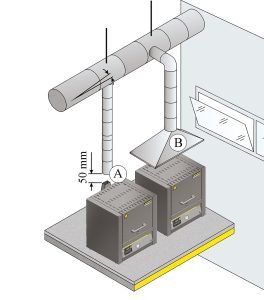
When exhaust gases are generated during the process it is mandatory to guide them outside in an adequate way. The relevant operating instructions must be always taken into consideration. When exhaust gas pipings are installed it is always necessary that a local ventilation technician lays out the system in accordance to the real environment.
There are different possibilities to guide the exhaust gases out. In many cases the furnace is positioned under a laboratory extraction provided by the customer. In these cases the use of an exhaust vent is recommended just to guide the gases upwards.
For this purpose metal exhaust gas pipes with NW 80 to NW 120 can be used. They must be installed continuously rising and fastened to the wall or ceiling. Center the pipe over the furnace vent (for models with vent fan or catalytic converter, NW 120 is necessary. The exhaust gas pipe must not be installed with a tight fit to the furnace vent pipe since this would prevent any bypass effect. This is necessary so that not too much fresh air is sucked in by the furnace.
Chimneys
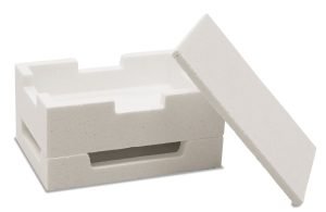
Square Saggar for Furnaces LHTC and LHT, Tmax 1600 °C
The load is placed in ceramic saggars for optimal utilization of the furnace space. Up to three saggars can be stacked on top of each other in the furnace. In models LHT 01/17 D and LHTCT 01/16 up to two saggars can be stacked. Each saggar has cut-outs for better ventilation. The top saggar should be closed with a lid made of ceramic.
Round Saggar (Ø 115 mm) for Furnaces LHT/LB, Tmax 1650 °C
These saggars are perfectly suited for furnaces LHT/LB. The load is placed in the saggars. Up to three saggars can be stacked on top of each other in order to use the overall furnace chamber.
Bottom Plates and Collecting Pans
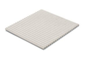
Select between different bottom plates and collecting pans for protection of the furnace and easy loading for models L, LT, LE, LV and LVT. Steel collecting pans may deform/distort under heat. For batches that are sensitive to tipping, ceramic shelves to protect the furnace bottom are recommended.
| For models | Ceramic ribbed plate | Ceramic collecting pan | Stainless steel collecting pan (Material 1.4828) | |||
|---|---|---|---|---|---|---|
| Articel No. | Dimensions in mm | Articel No. | Dimensions in mm | Articel No. | Dimensions in mm | |
| L 1, LE 1 | 691601835 | 110 x 90 x 12.7 | – | – | 691404623 | 85 x 100 x 20 |
| LE 2 | 691601097 | 170 x 110 x 12.7 | 691601099 | 100 x 160 x 10 | 691402096 | 100 x 180 x 20 |
| L 3, LT 3, LV 3, LVT 3 | 691600507 | 150 x 140 x 12.7 | 691600510 | 150 x 140 x 20 | 691400145 | 150 x 140 x 20 |
| L 5, LT 5, LV 5, LVT 5 | 691600508 | 190 x 170 x 12,7 | 691600511 | 190 x 170 x 20 | 691400146 | 190 x 170 x 20 |
| LE 6 | 691600508 | 190 x 170 x 12,7 | 691600511 | 190 x 170 x 20 | 6000095954 | 160 x 200 x 20 |
| L 9, LT 9, LV 9, LVT 9, N 7 | 691600509 | 240 x 220 x 12.7 | 691600512 | 240 x 220 x 20 | 691400147 | 240 x 220 x 20 |
| LE 14 | 691601098 | 210 x 290 x 12.7 | – | – | 691402097 | 210 x 290 x 20 |
| L 15, LT 15, LV 15, LVT 15, N 11 | 691600506 | 340 x 220 x 12.7 | – | – | 691400149 | 220 x 340 x 20 |
| L 24, LT 24 | 691600874 | 340 x 270 x 12.7 | – | – | 691400626 | 270 x 340 x 20 |
| L 40, LT 40 | 691600875 | 490 x 310 x 12.7 | – | – | 691400627 | 310 x 490 x 20 |
Gloves and Tongs
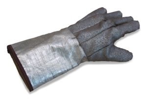
Heat-resistant gloves for protection of the operator when loading or removing hot materials, resistant to 650 °C or 700 °C.
