Furnaces for Special Applications
Furnaces for Special Applications
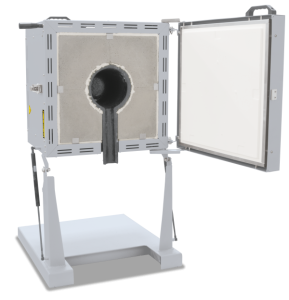
Gradient or Lab Strand Annealing Furnaces up to 1300 °C
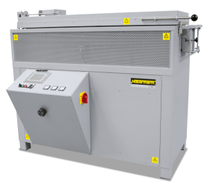
The furnace chamber of the gradient furnace GR 1300/13 is divided in six control zones of equal length. The temperature in each of the six heating zones is separately controlled. The gradient furnace is usually charged from the side through the parallel swivel door. A maximum temperature gradient of 400 °C can then be stabilized over the heated length of 1300 mm. On request the furnace also is designed as a lab strand annealing furnace with a second door on the opposite side. If the included fiber separator are used charging is carried-out from the top.
Standard Equipment
- Tmax 1300 °C
- Heated length: 1300 mm
- Heating elements on support tubes providing for free heat radiation in the kiln chamber
- Dual shell housing made of textured stainless steel sheets with additional fan cooling for low surface temperature
- Exclusive use of insulation materials without categorization according to EC Regulation No. 1272/2008 (CLP)
- Charging from the top or through the right side door
- Gas damper suspension of the lid
- Separate control of heating zones (each 160 mm long)
- Temperature gradient of 400 °C over the entire length of the kiln chamber, each zone can individually be controlled
- Fiber separators dividing the chamber in six equally sized chambers
- Defined application within the constraints of the operating instructions
- Controller H1700
- Up to ten control zones
- Second parallel swing door for use as lab strand annealing furnace
- Vertical instead of horizontal strand furnace
- 1400 °C model
- Process control and documentation via VCD software package for monitoring, documentation and control
| Model | Tmax | Inner dimensions in mm | Outer dimensions1 in mm | Connected | Electrical | Weight | ||||
|---|---|---|---|---|---|---|---|---|---|---|
| °C | w | d | h | W | D | H | load kW | connection* | in kg | |
| GR 1300/13 | 1300 | 1300 | 100 | 60 | 1660 | 740 | 1345 | 18 | 3-phase | 300 |
| 1External dimensions vary when furnace is equipped with additional equipment. Dimensions on request.*Please see page 75 for more information about supply voltage | ||||||||||
Fire Assay/Cupellation Furnaces up to 1300 °C
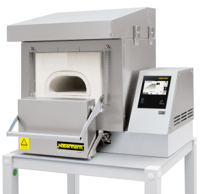
Cupellation is a process to separate precious metals, such as gold or silver, from alloys with base metals. During the process, aggressive gases that attack the insulation and the heating are released. Cupellation furnaces N ../13 CUP are especially designed for the very demanding process requirements.
The furnace chamber consists of a ceramic muffle, which offers very good protection for the heating elements and insulation against the vapors. A special fresh-air and exhaust air system guides exhaust gases directly into the exhaust hood of the cupellation furnace. At the same time, fresh air is lead into the furnace atmosphere. The integrated exhaust hood on top of the furnace and above the door is the interface to the customer’s required exhaust air system. The design is very-maintenance friendly; all wear and tear parts on the furnace, which are f.i. the ceramic muffle and the heating elements, can be replaced easily.
Cupellation furnaces N 4/13 CUP as a tabletop model and N 10/13 CUP are designed especially for cupellation. Due of its high chamber design, model N 30/13 CUP can also be used for crucible melting. Pit-type furnace S 73/HS is especially designed for crucible melting.
Standard Equipment of Cupellation Furnace N 4/13 CUP
- Compact tabletop model
- Dual shell housing made of textured stainless steel sheets with additional fan cooling for low surface temperature
- Exclusive use of insulation materials without categorization according to EC Regulation No. 1272/2008 (CLP)
- Ceramic muffle to protect the heating elements and insulation
- Furnace chamber is heated from three sides (floor and sides) with heating elements on support tubes
- Extraction system with integrated exhaust hood on top of the furnace and above the door to connect to the customer’s exhaust air system
- Manual lift door
- Defined application within the constraints of the operating instructions
- NTLog Basic for Nabertherm controller: recording of process data with USB-flash drive
Standard Equipment of Cupellation Furnaces N 10/13 CUP and N 30/13 CUP
- Ceramic muffle to protect the heating elements and insulation
- Dual shell housing made of textured stainless steel sheets with additional fan cooling for low surface temperature
- Exclusive use of insulation materials without categorization according to EC Regulation No. 1272/2008 (CLP)
- Furnace chamber is heated from 4 sides with heating elements on support tubes
- The heating elements can be easily replaced as one unit
- Furnace chamber ventilated as additional protection for the heating elements
- Precise temperature control with control thermocouple directly in the muffle
- Closing brick for the muffle with handle for N 10/13 CUP
- Electro-mechanic lift door for N 30/13 CUP
- Bench/surface in front of muffle
- Special fresh-air and exhaust air system for the ceramic muffle. Exhaust gases are directly guided into the exhaust hood via a ceramic tube at the back of the muffle. The air exchange rate is adjustable.
- Extraction system with integrated exhaust hood on top of the furnace and above the door to connect to the customer’s exhaust air system
- Over-temperature limiter with adjustable cutout temperature as temperature limiter to protect the oven and load
- Defined application within the constraints of the operating instructions
- NTLog Basic for Nabertherm controller: recording of process data with USB-flash drive
Standard Equipment of Pit-Type Furnace S 73/HS
- Compact pit-type furnace for crucible melting
- Dual shell housing made of textured stainless steel sheets with additional fan cooling for low surface temperature
- Exclusive use of insulation materials without categorization according to EC Regulation No. 1272/2008 (CLP)
- Split lid, opened manually by swiveling
- Heating from four sides
- Heating elements and floor protected against friction and aggressive substances with silicon carbide tiles
- Furnace chamber ventilated as additional protection for the heating elements
- Exhaust air box with insulated tube to the rear. Facilities for connection to customer’s necessary extraction system.
- Defined application within the constraints of the operating instructions
- NTLog Basic for Nabertherm controller: recording of process data with USB-flash drive
During the process, aggressive gases that attack the insulation and the heating are released. Cupellation furnaces N ../13 CUP are especially designed for the very demanding process requirements.
The furnace chamber consists of a ceramic muffle, which offers very good protection for the heating elements and insulation against the vapors. A special fresh-air and exhaust air system guides exhaust gases directly into the exhaust hood of the cupellation furnace. At the same time, fresh air is lead into the furnace atmosphere. The integrated exhaust hood on top of the furnace and above the door is the interface to the customer’s required exhaust air system. The design is very-maintenance friendly; all wear and tear parts on the furnace, which are f.i. the ceramic muffle and the heating elements, can be replaced easily.
Cupellation furnaces N 4/13 CUP as a tabletop model and N 10/13 CUP are designed especially for cupellation. Due of its high chamber design, model N 30/13 CUP can also be used for crucible melting. Pit-type furnace S 73/HS is especially designed for crucible melting.
Standard Equipment of Cupellation Furnace N 4/13 CUP
- Compact tabletop model
- Dual shell housing made of textured stainless steel sheets with additional fan cooling for low surface temperature
- Exclusive use of insulation materials without categorization according to EC Regulation No. 1272/2008 (CLP)
- Ceramic muffle to protect the heating elements and insulation
- Furnace chamber is heated from three sides (floor and sides) with heating elements on support tubes
- Extraction system with integrated exhaust hood on top of the furnace and above the door to connect to the customer’s exhaust air system
- Manual lift door
- Defined application within the constraints of the operating instructions
- NTLog Basic for Nabertherm controller: recording of process data with USB-flash drive
Standard Equipment of Cupellation Furnaces N 10/13 CUP and N 30/13 CUP
- Ceramic muffle to protect the heating elements and insulation
- Dual shell housing made of textured stainless steel sheets with additional fan cooling for low surface temperature
- Exclusive use of insulation materials without categorization according to EC Regulation No. 1272/2008 (CLP)
- Furnace chamber is heated from 4 sides with heating elements on support tubes
- The heating elements can be easily replaced as one unit
- Furnace chamber ventilated as additional protection for the heating elements
- Precise temperature control with control thermocouple directly in the muffle
- Closing brick for the muffle with handle for N 10/13 CUP
- Electro-mechanic lift door for N 30/13 CUP
- Bench/surface in front of muffle
- Special fresh-air and exhaust air system for the ceramic muffle. Exhaust gases are directly guided into the exhaust hood via a ceramic tube at the back of the muffle. The air exchange rate is adjustable.
- Extraction system with integrated exhaust hood on top of the furnace and above the door to connect to the customer’s exhaust air system
- Over-temperature limiter with adjustable cutout temperature as temperature limiter to protect the oven and load
- Defined application within the constraints of the operating instructions
- NTLog Basic for Nabertherm controller: recording of process data with USB-flash drive
Standard Equipment of Pit-Type Furnace S 73/HS
- Compact pit-type furnace for crucible melting
- Dual shell housing made of textured stainless steel sheets with additional fan cooling for low surface temperature
- Exclusive use of insulation materials without categorization according to EC Regulation No. 1272/2008 (CLP)
- Split lid, opened manually by swiveling
- Heating from four sides
- Heating elements and floor protected against friction and aggressive substances with silicon carbide tiles
- Furnace chamber ventilated as additional protection for the heating elements
- Exhaust air box with insulated tube to the rear. Facilities for connection to customer’s necessary extraction system.
- Defined application within the constraints of the operating instructions
- NTLog Basic for Nabertherm controller: recording of process data with USB-flash drive
Additional Equipment for Cupellation Furnace N 4/13 CUP
- Over-temperature limiter with adjustable cutout temperature as temperature limiter to protect the furnace and load
Additional Equipment for Cupellation Furnaces N 10/13 CUP and N 30/13 CUP
- Electro-mechanic lift door for N 10/13 CUP
- Swiveling inspection window as heat protection
- Timer to program switching on and off times (preset temperature)
- Base mounted on castors
Additional Equipment for Pit-Type Furnace S 73/HS
- Manual rolling lid
- Pneumatic rolling lid
- Over-temperature limiter with adjustable cutout temperature as temperature limiter to protect the furnace and load
- Timer to program switching on and off times (preset temperature)
| Model | Tmax | Inner dimensions in mm | Volume | Outer dimensions1in mm | Connected | Electrical | Weight | ||||
|---|---|---|---|---|---|---|---|---|---|---|---|
| °C | w | d | h | in l | W | D | H | load kW | connection* | in kg | |
| N 4/13 CUP | 1280 | 185 | 250 | 80 | 3.7 | 800 | 750 | 750 | 3 | 1-phase | 105 |
| N 10/13 CUP | 1300 | 250 | 540 | 95 | 8.0 | 800 | 1300 | 1850 | 15 | 3-phase | 450 |
| N 30/13 CUP | 1300 | 250 | 500 | 250 | 25.0 | 1050 | 1300 | 2150 | 15 | 3-phase | 480 |
| S 73/HS | 1300 | 530 | 380 | 360 | 73.0 | 1050 | 1530 | 900 | 26 | 3-phase | 890 |
| 1External dimensions vary when furnace is equipped with additional equipment. Dimensions on request.*Please see page 75 for more information about supply voltage | |||||||||||
Fast-Firing Furnaces up to 1300 °C
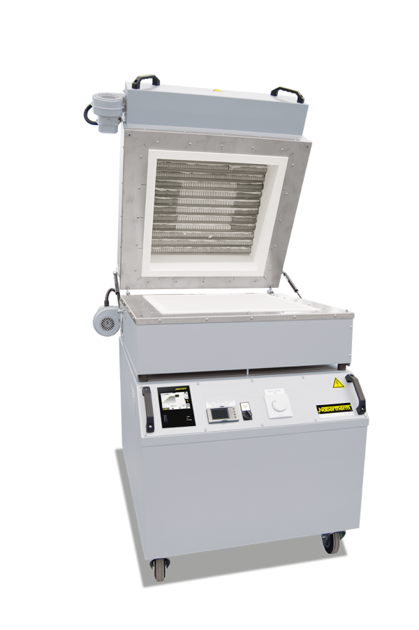
These fast-firing furnaces are ideal for simulation of typical fast-firing processes up to a maximum firing temperature of 1300 °C. The combination of high performance, low thermal mass and powerful cooling fans provides for cycle times from cold to cold up to 35 minutes with an opening temperature of approx. 300 °C.
Standard Equipment
- Tmax 1300 °C
- Ceramic grid tubes as charge support
- Floor and lid heating, two-zone control
- Special arrangement of the heating elements for optimum temperature uniformity
- Rapid switching cycles result in precise temperature control
- Dual shell housing made of textured stainless steel sheets with additional fan cooling for low surface temperature
- Exclusive use of insulation materials without categorization according to EC Regulation No. 1272/2008 (CLP)
- Integrated cooling fans, programmable to speed up charge cooling including housing cooling
- Programmable lid opening of approximately 60 mm for faster cooling without activating the fan
- Thermocouple type S for top and bottom zone
- Castors for easy furnace moving
- Defined application within the constraints of the operating instructions
- NTLog Basic for Nabertherm controller: recording of process data with USB-flash drive
- Controller P570 (50 programs with each 40 segments)
| Model | Tmax | Inner dimensions in mm | Volume | Outer dimensions2 in mm | Connected | Electrical | Weight | ||||
|---|---|---|---|---|---|---|---|---|---|---|---|
| °C | w | d | h | in l | W | D | H | load kW | connection* | in kg | |
| LS 12/13 | 1300 | 350 | 350 | 40 | 12 | 750 | 880 | 1090 | 15 | 3-phase1 | 150 |
| LS 25/13 | 1300 | 500 | 500 | 100 | 25 | 900 | 1030 | 1150 | 22 | 3-phase1 | 160 |
| 1Heating only between two phases*Please see page 75 for more information about supply voltage 2External dimensions vary when furnace is equipped with additional equipment. Dimensions on request. | |||||||||||
Laboratory Tilting Furnaces K/KC Electrically Heated
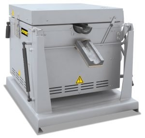
These compact tilting furnaces for the melting of non-ferrous metals and alloys are one of a kind and have a number of technical advantages. Designed as tabletop models, they can be used for many laboratory applications. The practical counter balanced hinge with shock absorbers and the spout (not for KC 4/14) on the front of the furnace make exact dosing easy when pouring the melt. The melting furnaces are available for furnace chamber temperatures of 1000 °C, 1300 °C, or 1400 °C.
- Tmax 1000 °C, 1300 °C, or 1400 °C
- Crucible sizes of 0.75 liters, 1.5 liters or 3 liters
- Dual shell housing made of textured stainless steel sheets with additional fan cooling for low surface temperature
- Exclusive use of insulation materials without categorization according to EC Regulation No. 1272/2008 (CLP)
- Crucible with integrated pouring spout of clay-graphite included with delivery
- Additional spout (not for KC 4/14), mounted at the furnace for exact pouring
- Compact bench-top design, simple emptying of crucible by tiltiing system with gas damper
- Crucible for heating up of melting furnace insulated with a hinged lid, lid opened when pouring
- Defined application within the constraints of the operating instructions
- Controller R7 (resp. 3508 for KC)
- Other crucible types available, e.g. steel
- Design as bale-out furnace without tilting device, e.g. for lead melting
- Over-temperature limiter for the furnace chamber with automatic reset to protect against overtemperature. The limit controller switches off the heating when the pre-set limit temperature has been reached and does not switch it on again until the temperature falls below the setting again.
- Observation hole for melt
| Model | Tmax furnace | Tmax melt bath | Crucible | Capacity | Volume | Outer dimensions3 in mm | Connected load | Weight | |||
|---|---|---|---|---|---|---|---|---|---|---|---|
°C | °C | in kg | in l | W | D | H | kW | in kg | |||
| Al | Cu | ||||||||||
| K 1/10 | 1000 | 850 | A6 | 1,5 | – | 0.75 | 600 | 710 | 670 | 3.0 | 85 |
| K 2/10 | 1000 | 850 | A10 | 3 | – | 1.50 | 600 | 710 | 670 | 3.0 | 90 |
| K 4/10 | 1000 | 850 | A25 | 7 | – | 3.00 | 670 | 800 | 710 | 3.5 | 110 |
| K 1/131 | 1300 | 1150 | A6 | 1,5 | 6 | 0.75 | 600 | 710 | 670 | 3.0 | 85 |
| K 2/131 | 1300 | 1150 | A10 | 3 | 10 | 1.50 | 600 | 710 | 670 | 3.0 | 90 |
| K 4/131 | 1300 | 1150 | A25 | 7 | 25 | 3.00 | 670 | 800 | 710 | 5.5 | 110 |
| KC 1/142 | 1400 | 1250 | A6 | – | 6 | 0.75 | 570 | 630 | 580 | 11.0 | 90 |
| KC 2/142 | 1400 | 1250 | A10 | – | 10 | 1.50 | 570 | 630 | 580 | 11.0 | 95 |
| KC 4/142 | 1400 | 1250 | A25 | – | 25 | 3.00 | 670 | 870 | 590 | 22.0 | 110 |
| 1Outer dimensions of furnace, transformer in separate housing (500 x 570 x 300 mm) 2Switchgear and controller mounted in a floor standing cabinet 3External dimensions vary when furnace is equipped with additional equipment. Dimensions on request. | |||||||||||
